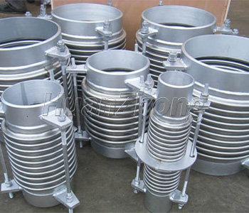
Pipeline compensator is subject to make use of the work of telescopic deformation effectively, to absorb the heat bilges cold shrink reasons such as the size of the change, different compensator to support also have different requirements, the following are several common brackets.
1, the main fixed bracket
Main fixed bracket is installed on one or a few no constraint on the piping of bellows expansion joint, it must abide by every section of connected to it on the force and moment exerted on it. Such as piping within the medium pressure produced by the thrust (blind plate force), displacement required to produce rated ripple compensator of the force and moment, and the adjustable guide bracket, directional guide bracket produced by friction, and the weight of the piping and medium, fluid impact, and so on. So when we choose unconstrained corrugated compensator, fixed bracket in the following conditions must be set:
1) pipe blind side
The flow direction of medium 2) change
3) pipe branch
4) pipe diameter changes
5) between the two corrugated compensator cut-off valve or valve in the pipeline.
2, fixed bracket
Here is what we call the time fixed bracket used to withstand except pressure thrust (blind plate force) the entire load. So for straight pipe, fixed support is usually in order to make a long section between two fixed bracket divided into several section unit, so that each section between only set a corrugated compensator, to guarantee the normal work of the corrugated compensator can.
3, guide bracket
Is set in the line guide bracket, is to ensure that the bellows expansion joint along the direction of displacement, and prevent the instability of the pipeline, the general guide bracket design strength by 10% - 15% of piping within the medium pressure thrust into account. On only axial displacement of the pipe section, guide bracket is only allowed axial displacement and the direction of the other limit displacement of the stents referred to as a general guide bracket, the section with the lateral displacement and deflection, in addition to the axial displacement, but should also in transverse set aside the appropriate additional margin, to allow a certain range of the lateral displacement and deflection, this guide bracket is called plane guide bracket.
4. Guide bracket spacing
For only the axial displacement of the occasions, the guide bracket spacing can be set up as follows: generally recommended, the expansion joint is close to a fixed bracket, the first end of the guide bracket and corrugated compensator spacing is not more than four times the diameter. This arrangement can make displacement getting the right guidance, but also make the inflated properly on both ends of bearing. The second guide bracket and the first guide bracket spacing is not more than 14 times of diameter.
